Beamed energy propulsion
The two big names in the field are Jordin Kare and Kevin Parkin. My contributions are usually about fitting beamed energy propulsion into the larger picture of power satellites.
However, once in a while I get into the technical calculations.
Numerical investigation of a Gausian power beam heating a surface cooled with hydrogen and re-radiating
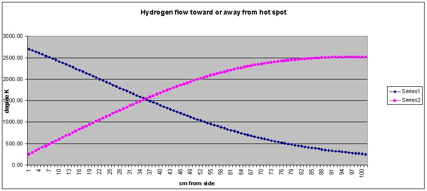
Given a gausian power distribution impinging on a surface cooled with flowing hydrogen, is it more efficient for the hydrogen to flow toward the high power center or away from it?
The attached file, image: Re_radiations gausian input.xls is an attempt to answer the question via a numerical model.
The model is of a one cm square tube by 100 cm element of a heater. The element analyzed is a right center 1 cm pipe of a 2 meter square microwave absorber subjected to a peak power density of 15.96 MW/m^2 and falling off on a gausian curve.
The effective radiation input on a square cm of the pipe is the radiation times the absorber efficiency ($A$2) less the radiation of the pipe, assumed to be 50 deg hotter than the flowing hydrogen inside it. The temperature gain is due to energy carried away by the hydrogen mass flow, ($E$1).
- q (kJ-s)
- DeltaT = ------------------------------------------
-
- Cp (kJ/kg-deg K) mass/s (kg/s)
The Cp for hydrogen is a function of temperature.
The results were clear; it is better to pump the hydrogen toward the hotter part of the gausian heating.
The advantage was about 200 degrees hotter hydrogen for pumping toward the hot spot. Although the peak re-radiation was higher, it was confined to a smaller area. Here is the .xls file.
Media:Re_radiation_gausian_input.xls
The 50 deg assumed ΔT from wall to the temperature of bulk hydrogen flowing in the channel was investigated further.
Viscosity and conductivity as well as density are all functions of temperature.
The equations were obtained here: http://www.osti.gov/bridge/servlets/purl/950459-XggUh7/950459.pdf
Velocity goes up ten fold as the absolute temperature increases ten fold. Based on the temperature, viscosity and conductivity are inserted into the model and from that Reynold's number, Prandtl's number and Nusselt's number are computed. The last gives the heat transfer coefficient for tubes per deg K between the wall and bulk gas temperature.
It turns out that the assumed 50 deg K is not enough. The column "excess wall area factor" is a measure of how much larger the wall (at 4 square cm/cm) would have to be to heat the hydrogen from the net input of heat. The heat transfer from the wll to gas will have to b improved.
While re-radiation is accounted for, the heat lost to the atmosphere while in it is not. This would be a very dynamic calculation since the vehicle would be accelerating rapidly to a velocity where skin friction exceeded the heater temperature.
To use this model, set the outlet temperature in Q9. Then adjust the hydrogen mass flow (E1) to get the inlet temperature in the 200-300 deg range.
Note that as of Sept 2011 this model has only been lightly checked. USE WITH CAUTION.
