Woozle's electronic learning kit No. 1 - sample circuits
Electronics: Woozle's electronic learning kit No. 1: parts and such
Introduction
You don't have to make these circuits in the same order they are shown here, but if you are having difficulty getting a circuit to work you might try making sure the one before it works for you.
Actually, you don't have to make any of these circuits at all; the ones shown here are really just to give you an idea of what you can do with just the few components in this kit. Feel free to be creative and try new ideas! But do remember just a couple of things when you are experimenting:
- Don't connect the two battery terminals together without a load between them, because this will drain the batteries very quickly and might make them get very hot (which could damage the holder or the wires), and might make the batteries start to corrode. A switch is not a load, and on the relay only the coil is a load.
- Always disconnect the battery when you are not experimenting. Even if the circuit doesn't seem to be doing anything, it may be draining the battery.
- Water and electronics don't get along. Stuff may still work if it gets wet, but the water may cause corrosion which will make things mysteriously stop working later on. Avoid getting electronic parts wet.
The "Duhhh" Circuit
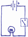
Ok, you probably know this one, but I'm putting it in here anyway (maybe not everyone knows it):
Part One
- connect an alligator clip to one of the battery leads
- pick a lightbulb
- connect the alligator clip at the other end of the wire to one of the leads of the lightbulb
- connect a different alligator clip to the other battery lead
- connect the other end of this alligator clip wire to the other lead of the lightbulb
- Result: the lightbulb should turn on (duhhhh!)
Part Two
- disconnect one of the alligator clips from a lightbulb lead
- connect it to one of the metal terminals on the back of the switch panel
- connect a different alligator clip to the metal terminal closest to the one you just connected
- connect the alligator clip at the other end of that wire to the unused lightbulb lead
- Result: if the lightbulb doesn't come back on when you connect the last wire, flip the switch and it should turn on
Tips:
- Make sure the metal part of the alligator clip is touching the bare metal part of the wire it is attached to, so electricity can flow from one to the other.
Testing the Relay
This is mainly to make sure the relay is working:
- connect an alligator clip to one of the battery leads
- pick a relay
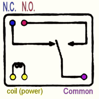
- connect the other end of the alligator clip wire to one of the relay terminals labeled "coil (power)" on the diagram
- connect another alligator clip to the other battery lead
- hold the alligator clip at the other end of that wire and brush it past the other "coil (power)" lead on the relay
- Result: the relay should make quiet "clicking" noises.
Relay Buzzer
Part One
- pick a relay
- connect an alligator clip to one of the "coil" leads on the relay
- connect the alligator clip at the other end to one of the battery leads
- connect another alligator clip to the other "coil" lead on the relay
- connect the alligator clip at the other end of that wire to the "N.C." lead on the relay
- connect one end of a third alligator clip to the other lead from the battery
- connect the other end of this alligator clip wire to the "Common" lead on the relay
- Result: the relay should buzz quietly
- disconnect the clip from the "Common" lead just for now, so we can build the next part of the circuit without that buzzing...
Part Two
- connect the alligator clip you just disconnected (from the "Common" lead) to one of the metal tabs on the back of the switch unit
- find an unused alligator clip wire (this will be the fourth one you'll be using) and clip it on to the metal tab closest to the one connected in the previous step
- connect the other end of this new alligator clip to the "Common" lead of the relay
- Result: if the relay doesn't buzz, then flip the switch and it should start.
Now you can turn your buzzer on and off without disconnecting anything :-)
Part Three
The short version: connect a capacitor in parallel with the relay coil. This holds the charge a little longer, so that the relay doesn't change states so quickly.
The step-by-step version:
- pick one of the capacitors
- connect an alligator clip to one side of the capacitor (Note: in some circuits it would make a difference which side you connected it to, but in this one it doesn't)
- connect the clip at the other end to one of the "coil" leads on the relay
- connect another alligator clip to the other side of the capacitor
- connect the other end of that alligator lead to the "N.C." lead on the relay (you can clip it to the alligator clip already there, if that is easier)
- reconnect the alligator clip from the battery to the relay's "Common" lead
- Result: depending on which capacitor you picked, you will either get a louder buzzing, a harsh rasping noise, or rapid clicking.
You can experiment with disconnecting and reconnecting the capacitor, or trying different capacitors to see what sound they make. (Hint: try the 350µF capacitor, if you haven't already) Or... how about connecting two capacitors at the same time?
More Circuits
Believe it or not, there are other circuits you can built with the kit. If you come up with any interesting circuits, feel free to post them on this web site – you can use the discussion page, email circuits@hypertwins.org or contact HTYP via the web site (htyp.org).


